Power and wiring
Pin tables for every port are in Baseboard ports.
Power
The unit takes power from POWER1, POWER2 or USB in the same order of priority.
Peripheral rails
The 5 V on the ports comes from two rails. Each rail has its own current limit and its own overcurrent flag, and the firmware can switch each one off.
| Rail | Feeds | Limit |
|---|---|---|
| VDD_5V_HIPOWER | TELEM1, GPS2 | 1.5 A |
| VDD_5V_PERIPH | TELEM2, TELEM3, CAN1, CAN2, CAN3, UART&I2C, GPS1, SPI, I2C, AD&IO | 1.5 A |
Servo rail
The board does not power VDD_SERVO. Feed it from an external supply at the voltage required by the servos. The board measures the rail, and the reading is valid only up to 9.9 V.
Connecting peripherals
Power module
Connect the power module to POWER1. A second module may be connected to POWER2. Each port has its own I2C bus, so identical I2C addresses on the two modules do not conflict.
GNSS and compass
Connect the GNSS module to GPS1. It has the UART, the I2C bus for the compass, and the safety switch pins. A second module goes to GPS2.
RC receiver
SBUS and PPM receivers connect to position 2 of RC IN / AUX. Spektrum receivers connect to DSM RC. The two share one input, so connect one receiver only.
Telemetry radio
Connect the telemetry radio to TELEM1. PX4 enables MAVLink on this port by default.
Motors and servos
On FMU PWM OUT, outputs 1 to 8 support DShot or PWM and outputs 9 to 12 support only PWM. The motor order depends on the airframe, see the PX4 airframe reference. Power the servo rail as described in Servo rail.
Companion computer
ETH is 100BASE-T1 over one twisted pair. The board is the PHY master, so the partner must be the slave. A computer with a standard RJ45 port needs a 100BASE-T1 to 100BASE-TX media converter.
PX4 asks DHCP for an address and falls back to the static address 10.41.10.2/24. The
board’s PX4 defaults start MAVLink on UDP port 14550 with broadcast on. A net.cfg file on
the SD card changes the address, see the
PX4 Ethernet page.
SD card
The slot is in the module. Logging, missions and the network configuration file require a card.
LEDs
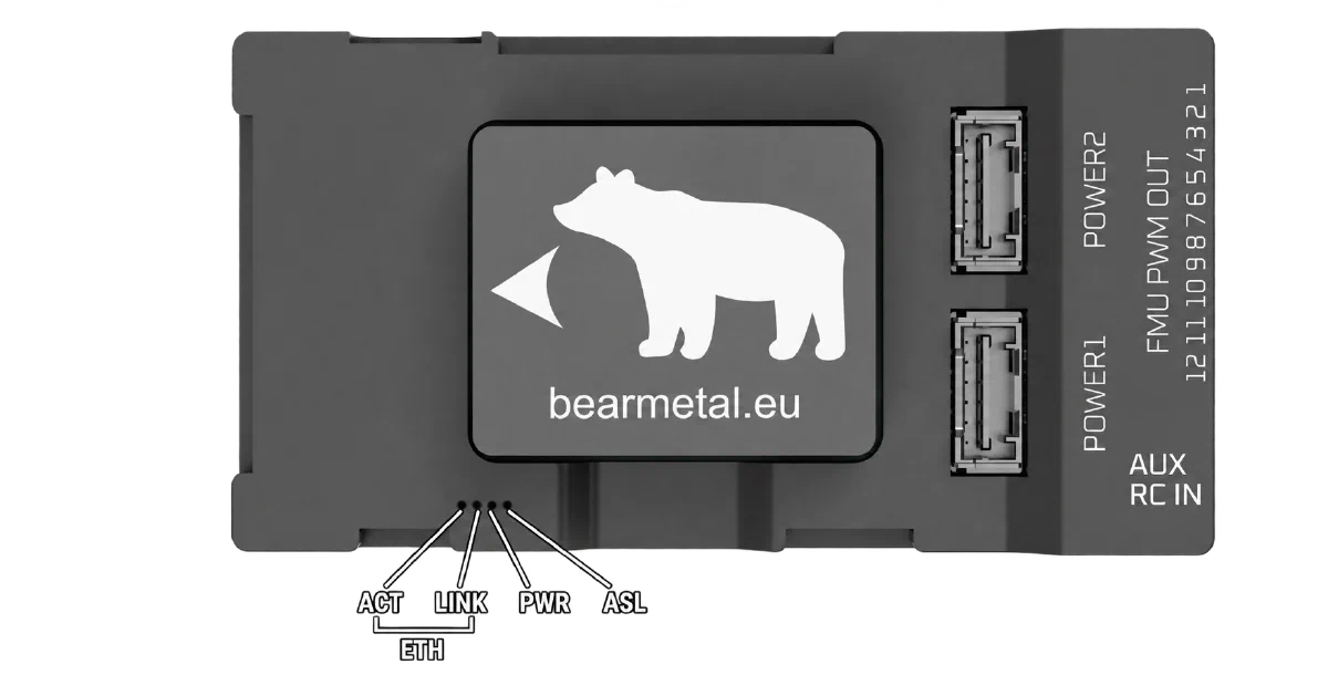
| LED | Meaning |
|---|---|
| ETH ACT | Ethernet activity—flashes when traffic is transmitted or received. |
| ETH LINK | A physical Ethernet link is established with another device on the 100BASE-T1 port. |
| PWR | Board power is present. |
| ASEL | Analog input selection—indicates which voltage source is routed to one of the flight controller’s ADC inputs. |
ASEL follows the analog multiplexer’s selection signal:
- Off: selects the external analog input on AD & IO connector J14, pin 7, labelled
ADC1_6V6. - On: selects servo-rail voltage (
VDD_SERVO) for measurement instead.